GEOMETRIC DIMENSIONING AND TOLERANCING - Part 1
What is Geometric Dimensioning and Tolerancing?
Geometric Dimensioning and Tolerancing (GD&T) is a critical aspect of engineering design and manufacturing. It is a system of symbols and notations used to define and communicate the shape, size, orientation, and location of parts and assemblies with a high degree of accuracy.

GD&T provides a standardized method for specifying and interpreting the geometric tolerance and dimensioning of parts, which can reduce errors, minimize production costs, and improve product quality and reliability. By using GD&T, engineers can define the exact specifications for each part of a product, ensuring that each part is manufactured to the correct size, shape, and position.
The fundamentals of GD&T, including its definition, purpose, advantages, and important ideas, will be covered in this introduction. This introduction will give you a strong basis to build on and allow you to comprehend the significance and advantages of adopting GD&T in engineering and manufacturing, regardless of your level of engineering experience.
2. What is an engineering drawing and its importance?
An engineering drawing is a technical illustration that visually communicates the design intent of a product or component. It is used by engineers and manufacturers to define the specifications and requirements of a product and to communicate this information to others involved in the product's design, development, and production.

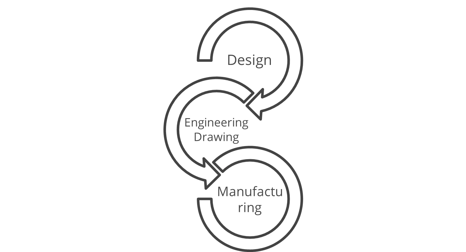
Figure 1: Process Flow – Part Development
The importance of engineering drawings
- Communication - Engineering drawings serve as a common language between engineers, designers, and manufacturers, allowing for clear and accurate communication of the product's design specifications.
- Design Documentation - Engineering Drawings provide a permanent record of the product's design, which can be used for reference and quality control throughout the product's life cycle.
- Manufacturing - Engineering Drawings provide the information necessary for manufacturers to produce the product according to the designer's specifications.
- Cost Reduction -Engineering Drawings help to reduce costs by minimizing the potential for errors, misunderstandings, and rework, which can be costly and time-consuming.
- Product Quality - Engineering Drawings help ensure that the product is manufactured to the correct specifications, leading to improved product quality and reliability.
In conclusion, Engineering Drawings are an essential tool for product design and development, providing the necessary information for successful product creation, and ensuring that the product meets its intended design criteria.
2.1. Quality of the drawing
Drawing should communicate:
- Physical dimensions of shapes and features with tolerances
- Material specifications
- Material treatment
- Critical functional details and requirements
- Important notes
Missing information or any error can adversely affect and cause an increase in the cost of the component.
3. Determining the tolerance for an application/ dimension
While determining the tolerance for an application/dimension several factors need to be considered to ensure the consistency in the output. Additionally selecting the tolerance is an iterative process. Below are some key considerations for effective tolerancing for an application/dimension,
- Design/Functional Requirements
Know the precise specifications and how the part or assembly works. Taking into account elements like fit, clearance, mated components, and overall performance objectives.

Figure 2: Deciding a tolerance for dimension
- Manufacturing Constraints
Analyse the manufacturing techniques and machinery that will be employed. Tolerances should be set within the range that these processes may reasonably achieve because different production techniques have inherent constraints. Below are steps to decide on a tolerance considering manufacturing constraints,
- arrive at a tolerance range depending on the manufacturing process and known generic precision of the process (Machining, Injection Moulding, Forging, Casting, Fabrication)
- identify general tolerance from International Tolerance (IT) Grade table from ISO 286 based on the manufacturing process
- tune the tolerance based on the functional requirements and mating relation
- consider tolerance stack up analysis if there is a combination of components or sub-assemblies
- finalise the tolerances after verifying the tolerance with respect to capability studies and actual production/real-time output.
4. Drawbacks of traditional / co-ordinate dimensioning system
- Inflexibility - The traditional coordinate dimensioning system is not flexible and does not accommodate changes in the design easily.
- Inefficiency - The manual process of dimensioning can be time-consuming and prone to errors.
- Lack of automation - Traditional dimensioning methods lack automation and rely heavily on manual processes, which can lead to increased errors and reduced productivity.
- Limited accuracy - The accuracy of the dimensioning process can be limited by the skill of the individual doing the work, leading to potential inaccuracies in the final product.
- Difficulty in understanding - The traditional dimensioning system can be difficult to understand for those not familiar with it, leading to confusion and misinterpretation.
- Inconsistent standards - The lack of standardization in the traditional dimensioning system can lead to inconsistencies in the final product and make it difficult to compare and assess the accuracy of dimensions across different products.
- Assembly consideration - No relatability of the dimensions when it comes to mating between two parts. No control of mating surfaces
- Geometric control -No geometric or profile can be controlled using traditional tolerancing. A special note should be mentioned for the same for manufacture.
5. Need for geometric tolerancing / why GD&T?
- Improved product quality - By specifying tolerances on specific features, geometric tolerancing helps ensure that parts will fit and function as intended, leading to improved product quality.
- Reduced rework and scrap - By providing clear and precise specifications for the tolerances of each feature, geometric tolerancing helps reduce the need for rework and scrap.
- Better communication - Geometric tolerancing provides a standardized language for communicating the desired tolerances between the designer, the manufacturer, and the inspector, which helps eliminate misunderstandings and improve communication.
- Increased efficiency - By providing clear and precise tolerancing specifications, geometric tolerancing helps streamline the manufacturing process, increase production efficiency, and reduce costs.
- Enhanced design flexibility - Geometric tolerancing allows designers to specify tolerances on a feature-by-feature basis, giving them more control over the design and increasing the flexibility of the design process.
- Improved quality control - Geometric tolerancing helps ensure that manufactured parts meet the specified tolerances, improving the overall quality control process.
6. How GD&T works?
GD&T works by using a set of symbols and rules to specify the allowable variation in geometric features on a part. The symbols and rules are defined in a standard called ASME Y14.5, which is widely used in the United States and other countries.
The basic elements of GD&T include:
- Geometric features - These are the physical features of a part, such as a hole, slot, or surface.
- Datums - These are reference points or planes on the part that are used to establish a coordinate system for measuring and tolerancing the features.
- Symbols - These are used to communicate the geometric tolerances and requirements for each feature. Some common symbols include position, concentricity, and parallelism.
- Tolerance zones - These are the allowable areas or volumes within which a feature must lie to be considered acceptable.
By using GD&T, engineers and designers can more accurately communicate the requirements for a part, which can help to reduce errors and rework in manufacturing. It also allows for more precise measurement and inspection of parts, which can lead to improved quality and performance.
7. Takeaways
In this blog, we explored Geometric Dimensioning and Tolerancing (GD&T) and its significance in engineering. GD&T is a standardized system that communicates part specifications accurately, ensuring proper fit and function.
We also learned about engineering drawings and their importance in effectively communicating design intent and guiding the manufacturing process. Understanding the quality of a drawing is crucial to avoid errors and ensure accurate representation.
Determining tolerances involves considering design requirements and manufacturing constraints. We discussed the drawbacks of traditional dimensioning systems and the need for GD&T, which provides improved product quality, efficient manufacturing, and better communication.
Lastly, we explored how GD&T works using symbols, rules, and tolerance zones to specify geometric features accurately.
Read the next part here
This blog is written by Basana Gouda, Senior Mechanical Engineer at Decos.
Decos is a cutting-edge technology services partner ready to meet your software needs in the medical domain. If you have a question on one of our projects or would like advice on your project or a POC, just contact Devesh Agarwal. We’d love to get in touch with you!

Discover more

Revolutionizing Rural Healthcare: How AI is Shaping the Future of Telemedicine

PFAS: How ‘Forever Chemicals’ Impact Medical Devices

